CFD Modeling Meets Wind Tunnel Design...and the Rest is History
By Kelly Hile
Experimentation is the driving force for technological advancement. It’s the year 1903, and Orville and Wilbur Wright have just taken flight at Kitty Hawk. Years later, in 1921, Orville reflects on the wind tunnel experiments that drove their success; it was one of the first few ever built. "I believe we possessed in 1902 more data on cambered surfaces, a hundred times over, than all of our predecessors put together."
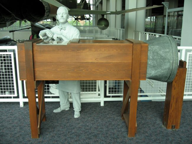
A replica of the Wright brothers' wind tunnel
The original uploader was Axda0002 at English Wikipedia., CC BY-SA 2.5, via Wikimedia Commons
Wind tunnels have been instrumental in the aerospace industry, not only from that first flight, but for many after, providing key data on lift and drag of aircraft components and allowing for greater control in the air. Eventually, other industries began employing this technology to improve product performance and test prototypes. Applications include automotive aerodynamics, wind flow analysis around tall buildings, sports equipment performance, and even calibration of flow instrumentation.
An accurate and reliable CFD simulation with Azore® can be like a “virtual” wind tunnel, driving innovation through simulated flow testing. Even though CFD technology is more practical than ever, we also know that simulations cannot fully replace physical testing and experimentation. The wind tunnel is still very alive today, and thanks to CFD, tunnels have higher accuracy and surprisingly creative applications. As fluid dynamics enthusiasts, we brim with nostalgia when we see Azore hard at work in wind tunnel design projects.
Customization is Key
Wind tunnels come in all shapes and sizes. A design facility or research lab usually has a very specific testing purpose, so a tunnel is often custom-made for its application. This includes not only the range of air velocity required for a test, but also the room size, the geometry of the prototype being tested, and data collection needs. Custom wind tunnel designs need to be evaluated to ensure they can deliver consistent, reliable flow to the test section.
The team that designed the wind tunnel pictured below used Azore to fine-tune each component for optimum performance. The tunnel now lives at an automotive research facility, where designers can evaluate vehicle cameras to see how they perform in various weather conditions. The test section delivers air velocities that emulate driving speeds up to 70 mph (112 kmh), and it features spray nozzles that simulate light to heavy rain.
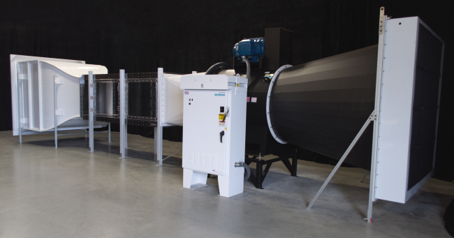
This custom wind tunnel with a built-in rain simulator was designed with the help of Azore.
A typical open-circuit wind tunnel design consists of a few basic components, which can vary in arrangement. In the configuration shown below, a settling chamber uses flow control devices to straighten the flow upstream of the contraction cone. The flow velocity increases as it narrows into the test section. The fan can be before or after the diffuser, which ensures fan efficiency and improves speed in the test section. CFD analysis is a great first step in proving out a design, allowing engineers to test out various geometries of all of these components in a virtual environment.
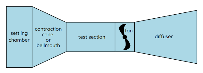
An open-circuit wind tunnel arrangement.
The Bellmouth
For the automotive wind tunnel, the design team was able to use Azore’s visualization and built-in data analysis tools to choose a bellmouth geometry. The CFD results showed how slight changes in the curvature of the bell would affect the downstream velocity profile in the test section.
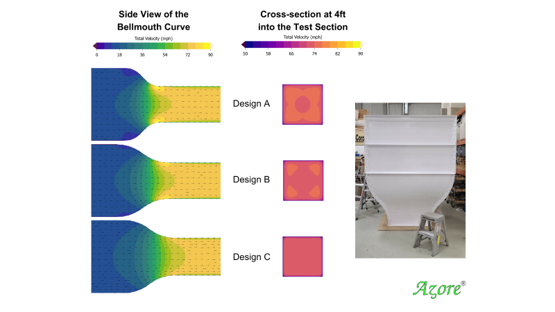
Design C achieved the most uniform velocity profile and influenced the final design (right).
The Test Section and Fan
The fan is the workhorse of the wind tunnel, driving the flow conditions within the tunnel. Additionally, the fan efficiency will drive the system efficiency and affect the ability of the test section to achieve a proper range of air velocities. Sizing a fan properly is just one step of this process; the designers must also ensure that the geometry around the fan will fully optimize the fan’s performance.
CFD simulations in Azore calculated the velocity and pressure conditions surrounding the fan. Azore can even quantify the work of the fan and supply data for calculating power requirements of the wind tunnel system.
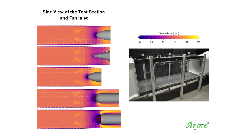
The design team explored the effects of adding a center body or cone at the center of the fan inlet, to help direct flow into the fan. The case at the far bottom shows the flow velocity without an inlet cone.
The Diffuser
The diffusion cone gradually slows down the air velocity in the tunnel so that the fan is working against a smaller pressure differential. Ultimately, a properly-sized diffuser ensures the fan is able to deliver higher velocities with less power. The team evaluated multiple geometry options at the fan outlet to determine how the pressure loss would be impacted by each.
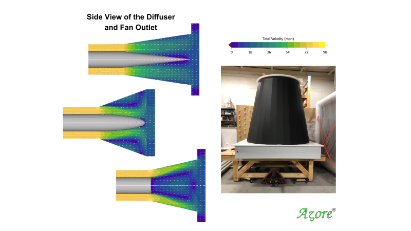
A center body at the fan outlet can help slow down the air velocity before it returns to the room. The bottom case shows the flow conditions without an outlet cone.
Design at the Component Level
This wind tunnel design process showcases the advantage of CFD modeling at the component level versus modeling the wind tunnel in its entirety. By breaking the design into smaller geometries, the team ensured that the models would be easy to modify and mesh without a huge time constraint. With over 20 separate CFD simulations completed for this wind-rain tunnel, component-level designs delivered faster run time and accelerated real-time feedback to the design team. Segmenting a design into smaller parts allows CFD engineers to isolate complex physics, geometry, or moving components. This means that other portions of the CFD modeling can be simplified and streamlined.
Azore has built-in features that allow simulation information to be passed from one component’s CFD model to the next. Data from the outlet of an upstream simulation can be easily imported as inlet conditions for the next downstream component. Any boundary conditions and solver settings from other similar models can also be saved and imported into a new case to drastically cut down on set-up time. Post-processing activities can be scripted for even faster processing of results, with fully-customizable visual tools and comprehensive data analysis. With this toolset in hand, this design team achieved a next-level wind tunnel design.
Looking Ahead
Wind tunnels have come a long way since those first experiments in the Wright Cycle Company shop. Armed with CFD analysis, the next generation of wind tunnels will certainly help fluid dynamics research take off into the future, and that’s a flight we are excited to watch.