Introduction
Learn how to set up a run in Azore CFD from start to finish in less than 30 minutes. This tutorial uses a model of an electronics cooling room or data center and gives a complete walkthrough of the Grid Menu and the Database Menu in Azore CFD.
What You'll Need
Several demonstration CFD models are included in the Azore installation files. The files needed for this tutorial are located in the directory AzoreCFD-Documents-->Azore-Tutorials-->3D-CoolingRoom.
Step 1: Import Mesh
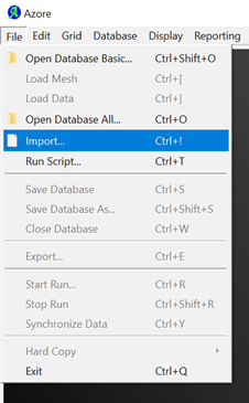
After launching Azore, choose File→Import and select the msh.gz file. Select File→Save Database As.
Step 2: Evaluate Grid
Navigate to Grid→Get Info. This gives general information about the grid and cell count. Navigate to Grid→Check grid to perform a check on the mesh. Verify that the extents of the model are as expected and make changes if needed. Choose Grid→Scale to change the grid scale with the factor 0.0254. Save the database.
Step 3: Define Physics
Navigate to Database→Equations to set the equations that will be used in the simulation. Select Standard K epsilon, and check the box to turn on energy. Set the fluid materials and properties by selecting Database→Fluid Materials. Change the density settings from constant to inverse w/ temperature.
Step 4: Set Boundary Conditions
Using the Database menu, set the boundary conditions for the exterior surfaces. For the inlet vents, click edit. Under Momentum, choose “specified mass flow” and set the mass flow at 6.6 kg/s. Under Turbulence, choose “intensity and hydraulic diameter” and set intensity at 0.05 and hydraulic diameter at 0.3 m. Under Energy, set the temperature to 290 K. Set the return vents as pressure boundaries with zero pressure. Change the boundary type of the walls on the electronic boxes to flow boundaries and set the flow rates and temperatures. Set the intake at -0.2 m/s, exhaust at 0.2 m/s and 325 K. Specify the effects of gravity on the fluid, -9.81 m/s in the y-direction. Select Solution Controls from the menu, and under the Energy tab, change the relaxation to 0.98. Change the temperature units to Celsius under Display→Units.
Step 5: Prepare Simulation Monitors
Set two surface monitors, one for the return vents and one for the rack intakes. Select Database→Solution Monitors→Surface and increase the number of monitors to 2. For the first monitor, click Surfaces and select return_vents and select Mass Weighted Temperature from the dropdown as the field to monitor. For the second monitor, select racks_intakes as the surface, and select Maximum Temperature as the field.